- Home
-
-

Energy Management and the Role of Smart Circuit Breakers
Views: 0 Author: Site Editor Publish Time: 2026-10-01 Origin: Site


Energy management is not simply a monthly utility exercise. For a facility team, it is the routine of seeing what a circuit is doing, deciding which loads deserve attention, and acting without compromising protection. A 2P Smart MCB can add communication and controllable switching to a low-voltage distribution point while retaining the familiar role of a miniature circuit breaker. That combination can make electricity use easier to investigate and manage, but it does not replace a sound panel design, correctly selected protection, or qualified electrical work.Key Takeaways
A smart breaker is most useful when its information and control functions are connected to a defined operating decision.
Two-pole isolation can suit circuits where line and neutral are intended to be switched together; the circuit design still determines the correct device.
Remote switching, schedules, and alarms can reduce unnecessary runtime only when teams assign owners and response rules.
Choose the communication method, current rating, trip curve, mounting arrangement, and control permissions before treating a device as an energy-management component.
Why energy management starts at the circuit
Most energy-management programs begin with a broad question: why did consumption change? Building-level data can expose a trend, but it may not reveal whether the driver is lighting left on after occupancy, a process load that starts too early, an HVAC branch with unexpected runtime, or a circuit that has become operationally critical. Circuit-level visibility narrows the investigation from a general bill to a practical operating conversation.
A 2P Smart MCB is not automatically a revenue-grade meter, an energy-management system, or a substitute for a protection study. Its useful role is more specific: it can become a controllable, connected point within a planned distribution architecture. When the selected device and platform provide the required data, operators can use that point to observe status, set approved schedules, receive a fault-related notification, or switch a non-critical circuit under an established procedure.
That distinction matters. Energy savings are created by operational changes such as eliminating avoidable runtime, staging loads, fixing abnormal behavior, or revising schedules. A connected breaker supplies a way to carry out and document some of those changes; it does not create savings merely by being installed.
What a 2P Smart MCB adds to a conventional protection point
A conventional miniature circuit breaker is selected for protective duty and manual isolation in its intended application. A smart model may add an electronics and communications layer that exposes operating status and enables controlled commands. The value is not that protection becomes optional; protection remains the first design requirement. The added layer can make a circuit easier to manage when a facility has recurring, approved decisions to make.
Long Road Electric describes its 2P ZigBee Smart MCB for industrial power distribution as an LRR6 device with remote opening and closing, local mode selection, timed operation, and ZigBee communication. The product page also lists 10A to 63A current options, 220/230VAC at 50Hz, Type C or D curves, and a 6kA breaking capacity. Those listed values are selection inputs, not a universal recommendation; the designer must confirm them against the actual circuit, coordination requirements, and local rules.
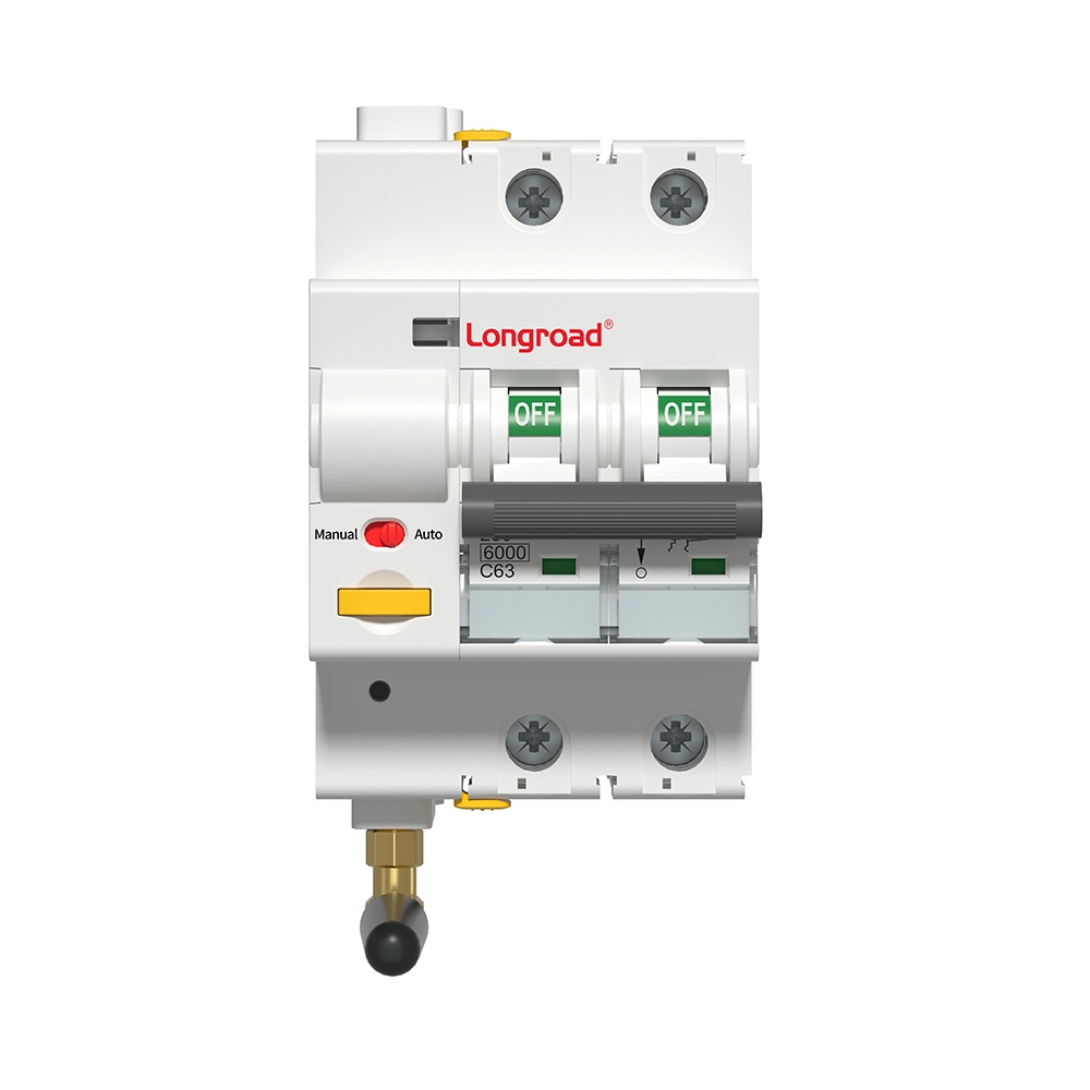
The “2P” label describes the pole configuration, not a complete application answer. A two-pole device can be relevant where both conductors are intended to be disconnected together. It should not be selected solely because it is connected or because an energy-management dashboard is desired. The panel arrangement, earthing system, loads, available neutral, wiring scheme, and applicable standard all matter.
Four practical roles in an energy-management workflow
1. Visibility and exception handling. Operators need a short path from an unexpected pattern to an action. A connected device can help identify a circuit that is on outside the approved window or that has changed state unexpectedly. The useful next step is not an automatic assumption; it is a defined check: verify the load, inspect the schedule, and decide whether switching or maintenance is appropriate.
2. Time-based operating control. Schedules can support predictable electrical loads, especially shared-area lighting, equipment with fixed operating windows, or temporary facilities. A schedule should be designed around operating needs, occupancy, safety functions, and override permissions. Do not schedule off a circuit that supports a life-safety, refrigeration, security, production, or IT load without a documented risk review.
3. Remote response for distributed sites. Remote access can shorten the time needed to confirm a breaker status or perform an approved switching action. It is most valuable when a local manual visit is otherwise required and when the operator can verify the condition of the connected load. Good practice is to state who may issue a command, when local confirmation is mandatory, and how an event is logged.
4. Integration with a broader control plan. The LRR6 product page lists ZigBee, WiFi, RS485, and dry contact among supported communication options for the 2P model. A project team should still test the chosen protocol, gateway, network coverage, account management, and loss-of-communication behavior in the actual environment. Integration is successful only when the device, wiring, control platform, and operating procedure work together.
A decision framework for specifying a 2P Smart MCB
Decision area
Questions to resolve
Why it affects the outcome
Protection and circuit duty
What are the voltage, current, prospective fault conditions, curve, and coordination requirements?
Connectivity must not drive selection ahead of verified protective suitability.
Pole and wiring arrangement
Does the circuit require simultaneous switching of both conductors, and does the panel provide the required connection arrangement?
The device must match the circuit topology rather than a generic automation preference.
Control objective
Is the goal status awareness, scheduled operation, remote switching, alarm routing, or a combination?
A clear objective prevents unused functions and unsafe blanket automation.
Communications
Which protocol, gateway, signal path, and cybersecurity controls are available?
Remote functions depend on reliable, governed connectivity.
Operations
Who can override, reset, acknowledge alarms, and change schedules?
Energy control needs accountability as well as equipment.
For projects that also need a conventional two-pole protective option, the LRM2-63 2P miniature circuit breaker page gives a useful baseline: it describes simultaneous line-and-neutral disconnection and lists AC applications from 1A to 63A. Comparing a conventional and connected device at the planning stage helps teams separate essential protection requirements from optional monitoring and control features.
Turning information into a repeatable management routine
A practical program needs a baseline. Record the circuit purpose, normal operating hours, responsible team, expected state outside those hours, and the permitted response to an alert. Then use the available device data and on-site checks to find exceptions. A weekend “on” indication may be an energy opportunity, a required service load, a commissioning issue, or evidence that the circuit label is wrong. The system should make the question easier to answer, not encourage a blind remote trip.
Next, make one controlled improvement at a time. Examples include changing the operating schedule for a clearly non-critical load, assigning an alarm recipient, or placing an approved manual/automatic mode rule around a seasonal process. Compare the result with the original expectation, document it, and retain local isolation and lockout procedures for maintenance. This loop is more durable than a one-time dashboard review.
Long Road Electric can be considered when a project needs a connected MCB that is compatible with its selected control architecture, but the purchasing decision should remain evidence-led. Confirm the exact model, voltage, current, communications option, protection setting, and application conditions with the current product documentation and the qualified project team.
Limits that should remain visible
Smart switching is not a permission to bypass electrical safety practice. A remote command cannot prove that a load is safe to energize, that a worker is clear, or that an abnormal condition has been corrected. Installation, commissioning, modification, and fault investigation belong to qualified personnel following applicable local regulations, manufacturer instructions, and site procedures.
Likewise, a device’s ability to communicate is not proof of metering accuracy, cyber resilience, or compatibility with every platform. Request the exact technical documents, verify interoperability in the proposed system, and decide how the circuit behaves when the network, gateway, or cloud service is unavailable. Local protective behavior, manual control, and clear recovery procedures are part of a resilient design.
How to measure whether the workflow is working
Measure the process before claiming a financial result. Useful indicators include the number of out-of-hours states investigated, the time from an unexpected indication to a verified response, the proportion of controlled circuits with current labels and owners, and the number of schedules that were reviewed after a change in occupancy or operating hours. These measures show whether the connected point is helping the team control the system deliberately.
Where energy data is available from a suitable measurement system, compare like-for-like operating periods and record the operational change that occurred. Avoid attributing a whole-site reduction to a breaker without evidence. Weather, production volume, occupancy, equipment replacement, and tariff structure can all affect the result. A disciplined record is more useful than an optimistic estimate because it tells the next project which control action was actually worthwhile.
From pilot circuit to portfolio practice
Many teams benefit from treating the first connected breaker as a pilot rather than a standard for every circuit. Select one circuit with a clear non-critical purpose, an accountable operator, a stable communications path, and a measurable operating question. Document the design decision, test the local and connected functions, and review the result after normal use. If the pilot adds useful clarity, the same naming, permission, schedule, and handover rules can be applied selectively to other suitable circuits.
This approach also exposes whether the limiting factor is hardware or process. A perfectly functional device cannot compensate for unknown circuit labels, absent owners, or a schedule that nobody is authorized to revise. Resolving those problems during a small deployment produces a more robust energy-management program than deploying connected products broadly and trying to govern them afterward.
Conclusion
A 2P Smart MCB is most valuable when it is treated as one managed point in a disciplined energy-control system. It can support circuit visibility, planned scheduling, controlled remote action, and integration with a wider platform, while the core breaker selection continues to be driven by the electrical design. Start with the operating decision that needs to improve, select the device for the actual circuit, verify the communications path, and give operators explicit authority and limits. That approach turns connected protection hardware into a useful energy-management tool rather than an isolated feature.
FAQs
What is the role of a 2P Smart MCB in energy management?
A 2P Smart MCB can provide a connected control and status point for an appropriately designed circuit. It may support scheduled operation, remote switching, or integration with a management platform, but it does not by itself guarantee energy savings or replace protective design.
Can a smart breaker replace an energy meter?
Not necessarily. Metering purpose, accuracy class, data requirements, and billing or reporting obligations must be evaluated separately. Use the exact model documentation to determine what data the device supplies and whether a dedicated meter is required.
When should a two-pole smart breaker be considered?
Consider it only when the circuit design calls for two-pole operation and the selected device meets the verified electrical and installation requirements. The pole count should follow the wiring and safety design, not a preference for remote control.
Can a 2P Smart MCB be used with ZigBee and RS485?
The supplied LRR6 2P product page lists ZigBee and RS485 among its supported communications. Confirm the exact ordered version, gateway, addressing, and integration method before specifying it for a project.
Will remote switching reduce a facility's electricity cost?
It can enable actions that reduce avoidable runtime, such as applying an approved schedule to a non-critical circuit. Savings depend on the load, operating behavior, tariff, and execution; remote switching itself is not a quantified saving claim.
Who should install and commission a smart MCB?
Installation and commissioning should be carried out by qualified electrical professionals in accordance with the device instructions, the panel design, and applicable local requirements. Remote features should be tested only after the protective and wiring checks are complete.