- Home
-
-

What Is a Smart Circuit Breaker? Why Use a 4P Smart MCB?
Views: 0 Author: Site Editor Publish Time: 2026-10-22 Origin: Site


A smart circuit breaker is a circuit-protection device with an added communications and control layer. Depending on the exact model and system, that layer can support visible operating status, remote commands, schedules, or integration with a building or distribution platform. A 4P Smart MCB applies the same connected-management idea to a four-pole configuration. It is not a universal upgrade for every panel; its value comes from matching the right pole arrangement, protection characteristics, and control objective to a real distribution application.Key Takeaways
A smart circuit breaker combines an appropriate protective device with model-specific communications and management functions.
4P describes a four-pole configuration; it must be selected from the circuit design, not from a preference for more poles.
Remote status and switching are useful only with safe control boundaries, verified communications, and qualified commissioning.
Compare the exact model’s electrical specifications and supported interfaces with the project requirements before purchase.
What makes a circuit breaker “smart”?
The word “smart” should be treated as a functional description, not as a safety claim. In a conventional arrangement, a miniature circuit breaker is selected to provide protection and manual operation within stated ratings. A connected version may make some information or controls available outside the panel: for example, an approved operator may see a state, apply a schedule, or issue a remote command through a supported interface.
The device therefore sits at the intersection of electrical distribution and operations. Its protection role is still defined by ratings, curve, fault duty, wiring, coordination, and standards. Its smart role is defined by communications, gateways, credentials, platform configuration, user permissions, and a procedure for responding to an event. A successful project respects both layers.
What does 4P mean—and why does it matter?
4P means the device has four poles. The right interpretation depends on the system configuration and the function required by the electrical design. It can be relevant to multi-conductor or multi-circuit arrangements where the design calls for coordinated switching or isolation. It does not mean that four-pole devices are inherently safer, more capable, or appropriate for a particular application without further analysis.
Before selecting a 4P Smart MCB, the responsible design team should define the supply and load arrangement, conductor roles, neutral treatment where applicable, voltage and current conditions, protective coordination, available fault level, and local regulatory requirements. The model must then be checked for the applicable AC or DC use. Do not use a four-pole DC product as proof of suitability for an AC smart-distribution application, or vice versa.
Why use a 4P Smart MCB in a distribution project?
The case for a 4P Smart MCB is strongest when two needs coincide: the distribution design requires a four-pole device, and the operations team has a specific reason to manage that point through a connected system. Those reasons can include confirming a controlled state at a remote site, placing an approved operational schedule around a defined non-critical load, coordinating a distribution action with a building-management workflow, or providing a clear escalation path when the device reports an abnormal condition.
A four-pole smart device should not be chosen merely to create a more sophisticated dashboard. If the circuit is simple, local, and does not need managed control, a conventional device may be the cleaner choice. Conversely, if the circuit supports a critical service, the remote-control design needs particularly careful review. The ability to operate a circuit from a distance never removes the need to understand what that circuit energizes.
How to compare a 4P Smart MCB with other options
Option
Potential role
Selection boundary
Conventional 4P MCB
Protection and local switching in an appropriate four-pole circuit.
Use when connected monitoring or control is not needed.
4P Smart MCB
Appropriate four-pole protection plus specified connected management functions.
Use only when the electrical design and control architecture are both verified.
1P or 2P Smart MCB
Connected management for a circuit designed around fewer poles.
Do not substitute pole counts without engineering review.
Dedicated monitoring or control equipment
Supplemental functions in a broader panel architecture.
May be required where breaker functions do not satisfy the system need.
Long Road Electric provides a 4P ZigBee Smart MCB for building electrical distribution as a relevant product reference for the category. Use the current product page and technical documentation to verify the precise pole arrangement, ratings, communication options, installation requirements, and intended application before specification.
Connected functions need an operating plan
Every smart function should lead to a defined decision. If a team wants remote status, establish what status is meaningful, who observes it, and when a site visit is required. If it wants a schedule, identify the approved operating window and the override process. If it wants an alarm, decide who receives it, the response time, and whether an alarm indicates a fault, a state change, or merely a communication issue.
Then plan the communications path. Check protocol compatibility, gateway placement, device naming, account ownership, network access, and behavior during a loss of connection. Local protective operation, manual control, and safe recovery should be understood before the system is handed over. The connected layer must improve operational clarity rather than introduce ambiguity.
Where four-pole thinking also appears in DC systems
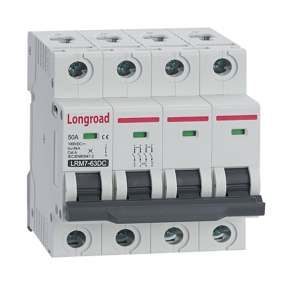
Some projects involve four-pole configurations for high-voltage DC photovoltaic arrangements, which are a distinct application from a smart AC MCB. Long Road Electric’s LRM7-63DC 4P MCB DC1000V page describes a dedicated PV DC device for dual-string, bipolar, and high-power PV applications. This comparison is useful because it shows why application context matters: a pole count alone is not enough to determine suitability. AC/DC duty, arc interruption, voltage, standards, and circuit topology all need separate verification.
Procurement questions that prevent rework
Ask for the exact model code and current documentation. Confirm whether the rated voltage, current options, breaking capacity, trip characteristic, mounting, dimensions, and environmental limits match the panel. Ask which protocol and gateway are required, whether the integration is local or cloud-based, and how access is managed. Define whether the project needs status only, remote switching, scheduling, or an interface to a BMS. Finally, define the commissioning tests and the handover record.
Long Road Electric is relevant to projects seeking MCB and smart-breaker options, but procurement should remain application-specific. Do not claim a capability, certification, or compatibility until it has been verified in the current product documentation and project design.
Commissioning a four-pole connected point
Commissioning should verify more than successful device enrollment. The qualified team should confirm that the installed model matches the approved design, the pole arrangement and terminal connections are correct, the circuit is labelled accurately, and the device’s local operating behavior is understood. The control side then needs its own checks: correct device name, correct gateway or network path, limited user access, intended indications, approved remote functions, and known behavior if communications are lost.
Keep this test staged and controlled. A four-pole device can be associated with a substantial distribution function, so an uncontrolled remote command is not a good commissioning method. Plan the test condition, affected load, observers, stop criteria, and restoration process beforehand. The aim is to verify the whole approved workflow without creating an unplanned interruption or energization.
Information to include in an RFQ or technical review
Provide the system type, intended voltage and frequency or DC duty, required pole configuration, rated current, expected fault conditions, trip characteristic requirements, mounting environment, panel constraints, and the code or standard framework. Describe the connected function separately: protocol, gateway, platform, desired status or control points, account and cybersecurity requirements, and whether remote switching is permitted. This makes supplier responses comparable and prevents a quotation from being evaluated only on headline features.
Also ask for the current installation instructions, drawings, datasheet, dimensions, environmental limits, supported communication interfaces, and the precise scope of any remote or automatic function. If the project needs integration with a BMS, PLC, or property platform, define who will prove interoperability and what the acceptance test looks like. These questions turn a generic “smart breaker” request into a specification that can be engineered.
Maintenance and change control
After handover, maintain the physical and digital record together. Any change to a schedule, user role, circuit label, gateway, or application account can alter how the system is used even when the breaker has not changed. Record the change, review the control boundary, and make sure local panel labels remain aligned with the displayed name. For planned maintenance, use the site’s approved isolation method; an app command is not a substitute for lockout and verification.
This discipline is especially important when a property changes use or a facility tenant modifies equipment. The original four-pole device selection may still be correct, but the operational logic could no longer be. Periodic review keeps the connected layer tied to the real circuit rather than to a historic assumption.
Keep the smart function proportional to the risk
The more significant the connected load or distribution point, the more carefully the project should define control boundaries. Remote visibility may be helpful even when remote switching is restricted. A schedule may be acceptable for one load and prohibited for another. This is why connected functions should be reviewed individually rather than enabled merely because the device advertises them.
Proportional control also makes handover clearer. Operators should know which actions are permitted, which need local confirmation, and which require an electrical authority. By linking each smart feature to a specific approved workflow, the project keeps the benefits of connectivity without making the distribution system harder to govern.
Separate product claims from project decisions
A datasheet can describe the functions and stated ratings of a particular product. It cannot decide whether the product is correct for a specific building, panel, load, or control strategy. Keep those decisions separate in the project record: one document verifies the product, while the design and commissioning documents verify its use. This separation makes procurement more transparent and reduces the risk of turning general marketing language into an untested site requirement.
Plan for clear operator visibility
Where a four-pole connected device is included in a management platform, its displayed name and location should be meaningful to the people who operate the site. Use the same naming convention in the panel, drawings, commissioning record, and platform. Clear identification speeds a safe response and reduces the chance of a command being directed at the wrong distribution point. It is a small design task with a large effect on day-to-day usability.
Conclusion
A 4P Smart MCB is a connected protective device intended for a circuit that genuinely calls for four-pole operation and a managed control point. Its benefit is not the number of poles or the presence of an app. Its benefit is a better-defined operating process: clear status, appropriate control, documented roles, and a device selected correctly for the distribution system. Start with the circuit, prove the electrical fit, then decide whether connectivity solves a real operational problem.
FAQs
What is a 4P Smart MCB?
It is a smart miniature circuit breaker in a four-pole configuration. The exact protective and connected functions depend on the specific model and must be verified against the circuit design.
Is a 4P Smart MCB suitable for every three-phase panel?
No. Pole arrangement, neutral treatment, ratings, fault conditions, standards, and control requirements must all be assessed by qualified professionals for the particular panel.
Can a 4P Smart MCB provide remote switching?
Some models may list remote-control functions. Confirm the exact model, communications architecture, site permissions, and safe operating procedure before relying on remote switching.
Does a 4P Smart MCB replace a BMS?
No. It may be one connected field device within a wider system. A BMS or other platform has separate requirements for integration, data, control logic, alarms, and cybersecurity.
Can a DC 4P MCB be used instead of an AC 4P Smart MCB?
Not by default. AC and DC applications have different interruption, voltage, topology, and standards considerations. Select only the device approved for the intended application.
Who should commission a 4P smart breaker?
Qualified electrical and controls personnel should commission it under the approved project procedures, including protection checks, wiring verification, communications tests, and controlled functional testing.