- Home
-
-

Can I Replace a Circuit Breakers?
Views: 0 Author: Site Editor Publish Time: 2026-07-20 Origin: Site


✅ Yes, a qualified electrical professional or experienced technician can replace a Circuit Breaker provided proper safety protocols, busbar power isolation standards, precise electrical panel specification matching, and accurate overcurrent protection ratings are strictly maintained during the replacement procedure.
At a Glance
Section
Summary
Signs That Point to Replacing a Circuit Breaker
Identifies critical physical, electrical, and thermal indicators—such as nuisance tripping, physical scorching, elevated contact resistance, and mechanical latch failure—that signal an immediate imperative for device replacement.
Benefits of Replacing a Circuit Breaker
Outlines the multifaceted advantages of replacing aged units, including restored system reliability, reduced fire risk, enhanced energy efficiency, and integration of smart remote monitoring features.
Tools Needed for a Circuit Breaker Replacement
Details the essential specialized tools, calibrated testing instruments, and Personal Protective Equipment (PPE) required to execute a safe and compliant replacement procedure.
How to Replace a Circuit Breaker
Provides a rigorous, step-by-step engineering roadmap detailing power isolation, voltage verification, panel disassembly, conductor torque verification, and post-installation diagnostic testing.
Delving Deeper: What Kind of "Upgrade" Are We Talking About?
Explores advanced technological evolutions, contrasting conventional thermal-magnetic units with modern intelligent electronic trips and smart ZigBee power distribution solutions.
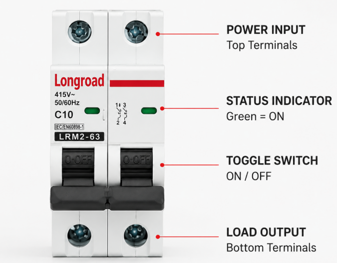
Signs That Point to Replacing a Circuit Breaker
Replacing a Circuit Breaker becomes strictly necessary when the unit demonstrates physical structural damage, persistent thermal overheating exceeding allowable operating limits, mechanical latching mechanism failure, or repeated tripping under normal calibrated load conditions.
In high-density power distribution panels, a Circuit Breaker relies on delicate bimetallic strips for inverse-time overload protection and electromagnetic solenoids for instantaneous short-circuit clearing. Over extended operating cycles, continuous current exposure combined with harmonic distortions and ambient thermal spikes causes subtle metallurgical shifts in the bimetal strip. This physical wear alters its time-current trip curve characteristics, leading to nuisance tripping under currents well below the nominal frame rating. Furthermore, repeated arcing during short-circuit interruption gradually erodes the copper-silver alloy contacts within the arc chute, resulting in elevated internal resistance and severe localized heat dissipation.
Engineers and maintenance teams must continuously monitor the electrical distribution enclosure using calibrated infrared thermography and digital insulation resistance meters. When thermal imaging reveals localized hot spots across terminal clamps or the breaker housing exceeding normal temperature rise thresholds (typically above 60°C over ambient), it indicates contact surface oxidation or terminal loosening. Continued operation under severe thermal distress breaks down the molded plastic casing, leading to plastic embrittlement, carbon tracking, and severe dielectric failure between adjacent phases or ground path elements.
Beyond electrical and thermal anomalies, physical and mechanical degradation presents an immediate safety risk. If the manual toggle switch feels spongy, fails to lock securely into the "ON" position, or remains unresponsive after clearing a downstream trip event, the internal spring-loaded trip latch mechanism has suffered mechanical fatigue or structural deformation. Operating a compromised Circuit Breaker risks prolonged fault clearing times, severe equipment damage, arc flash occurrences, and catastrophic electrical panel fires.
Diagnostic Parameter
Normal Operating Baseline
Replacement Indicator Threshold
Primary Root Cause
Terminal Temperature Rise
< 30°C above ambient
> 60°C above ambient / visible discoloration
Contact oxidation, loose connection torque
Insulation Resistance (500V DC)
> 100 MΩ
< 5 MΩ between phase and frame
Dielectric degradation, carbon tracking
Contact Voltage Drop (at nominal current)
< 50 mV
> 150 mV across poles
Eroded contact surface, spring tension loss
Trip Function Response
Conforms to standard time-current curve
Immediate trip under sub-nominal load or failure to trip
Fatigued bimetal strip, welded contacts
Key Maintenance Tip: Regular annual infrared thermal scanning combined with primary or secondary current injection testing ensures that aging protective devices are identified and replaced prior to catastrophic dielectric breakdown or operational disruption.
Benefits of Replacing a Circuit Breaker
Replacing an outdated or faulty Circuit Breaker significantly elevates electrical system safety, restores precise overcurrent protection parameters, eliminates unexpected downtime, and enables the integration of advanced smart power distribution capabilities.
The primary engineering benefit of replacing a legacy protective unit lies in the restoration of precise time-current trip characteristics. Over time, physical wear disrupts the calibrated gap within the electromagnetic trip unit and degrades the bimetallic spring tension. By installing a freshly calibrated modern unit, system designers ensure that downstream branch conductors are protected strictly within their thermal withstand limits. Modern manufacturing practices utilize precision alloy contacts and high-efficiency arc chutes designed to quench electric arcs within milliseconds, significantly reducing total let-through energy during severe short-circuit events.
From an operational continuity and energy management perspective, replacing traditional standalone protection devices with modern intelligent modules creates immense value for facility operators. Modern installations frequently integrate high-performance energy monitoring and automated circuit control systems. For instance, incorporating a modern 2P Smart MCB ZigBee Industrial Power Distribution module into commercial or industrial sub-panels enables real-time voltage, current, power factor, and leakage current telemetries to be continuously transmitted to centralized energy management platforms. This transition transforms a passive protective box into an active diagnostic node.
Furthermore, upgrading to modern Circuit Breaker units substantially mitigates arc flash boundaries and reduces overall fire safety hazards within industrial facilities. Modern units maintain precise mechanical tolerances and incorporate self-diagnostic electronics or arc fault detection logic that traditional thermal-magnetic breakers lack. Consequently, replacing compromised devices lowers overall maintenance expenditure, eliminates expensive emergency troubleshooting caused by intermittent tripping, and ensures full compliance with evolving international standards such as IEC 60947-2 and national electrical installation codes.
Performance Attribute
Legacy / Degraded Circuit Breaker
Modern Replacement Unit
Operational Advantage
Arc Quenching Time
15 ms to 25 ms
3 ms to 8 ms
Drastically reduced $I^2t$ let-through energy
Trip Accuracy Variance
± 20% to 30% shift over time
± 5% calibrated precision
Prevents nuisance tripping and conductor damage
Monitoring & Telemetry
None (passive analog)
Digital voltage, current, energy reporting
Enables predictive maintenance and automation
Remote Control Capabilities
Manual toggle operation only
Motorized remote switching & schedule control
Supports intelligent load shedding and automation
Tools Needed for a Circuit Breaker Replacement
Executing a compliant Circuit Breaker replacement demands specialized electrical hand tools, calibrated measurement instruments, personal protective equipment, and torque-calibrated drivers to guarantee zero-energy safety and verified contact pressure.
Electrical safety standards mandate strict Lockout/Tagout (LOTO) procedures prior to initiating any work inside a power distribution panel. To perform a replacement, technicians must utilize a rated digital multimeter or non-contact voltage detector rated for CAT III or CAT IV environments to independently verify that all line-side and load-side terminals are completely de-energized. Additionally, VDE-certified 1000V insulated hand tools—including flathead and Phillips screwdrivers, needle-nose pliers, and wire strippers—are mandatory to protect personnel against accidental contact with adjacent live busbars.
Beyond standard hand tools, achieving long-term mechanical and electrical connection stability requires precise torque control. Loose terminal connections represent one of the leading causes of localized heating, thermal runaway, and electrical fires in distribution panels. Therefore, a calibrated torque screwdriver or torque wrench calibrated in Newton-meters (N·m) or inch-pounds (in-lbs) is essential. Technicians must strictly apply the manufacturer's specified tightening torque values to line clamps, neutral blocks, and load terminal screws during installation.
Personal Protective Equipment (PPE) forms the final non-negotiable layer of protection during the replacement procedure. Depending on the calculated arc flash hazard boundary of the electrical panel, technicians must wear NFPA 70E-compliant arc-rated face shields, flame-resistant (FR) protective apparel, insulated rubber gloves with leather protectors, and safety footwear. Utilizing proper protective gear ensures complete safety in the event of unexpected voltage transients or mechanical busbar failures.
Tool / Equipment Category
Specific Item Name
Key Technical Specifications
Primary Application Purpose
Testing Instruments
Digital Multimeter / Voltage Tester
CAT III 1000V / CAT IV 600V certified
Zero-energy verification (Phase-Phase, Phase-Ground)
Insulated Hand Tools
1000V Insulated Screwdriver Set
IEC 60900 / VDE certified blades
Safe removal and securing of terminal screws
Fastening Calibration
Adjustable Torque Screwdriver
0.5 N·m to 5.0 N·m range (± 4% accuracy)
Applying exact manufacturer clamping torque
Personal Protection (PPE)
Arc-Rated Safety Gear & Gloves
Class 0 (1000V) rubber gloves + FR clothing
Personnel protection against flash and electrical shock
Safety Controls
Lockout / Tagout (LOTO) Kit
Padlocks, breaker lock clamps, warning tags
Physical isolation of upstream supply breakers
How to Replace a Circuit Breaker
To replace a Circuit Breaker safely, one must systematically isolate upstream power, verify zero voltage, disconnect load wiring, unlatch the unit from the DIN rail or busbar, install the exact replacement device, apply verified terminal torque, and complete post-commissioning insulation tests.
The replacement process begins with comprehensive preparation and de-energization. First, open the upstream main supply isolator or main Circuit Breaker feeding the distribution board. Apply a standardized Lockout/Tagout lock and hazard tag to the main switch mechanism to prevent unauthorized re-energization during maintenance. Remove the distribution panel dead-front cover plate to expose the internal wiring chassis. Using a calibrated digital multimeter, perform a three-point voltage test (testing live-to-neutral, live-to-ground, and phase-to-phase) on the incoming supply terminals to definitively confirm the complete absence of electrical potential.
Once zero energy is verified, proceed with disconnecting the branch circuit conductors connected to the target unit. Using an appropriately sized insulated screwdriver, loosen the terminal clamping screws on the load side of the Circuit Breaker. Carefully extract the phase conductor (and neutral conductor, if replacing a multi-pole or neutral-switching unit) from the terminal cage, inspecting the wire copper strands for oxidation, thermal discoloration, or mechanical necking. If conductor degradation is evident, strip the wire end back to clean, untarnished copper before retermination. Unclip the damaged breaker from the standard 35mm DIN rail or unbolt it from the panelboard busbar assembly depending on the mounting architecture.
Mount the new, appropriately rated replacement unit onto the DIN rail, ensuring the spring-loaded mounting clip firmly snaps into position. Insert the line-side busbar connector and load-side circuit wires deeply into their respective terminal cages. Using a calibrated torque screwdriver, tighten all terminal screws precisely to the manufacturer's specified torque rating (typically 2.0 to 2.5 N·m for standard miniature protective devices). In smart commercial or industrial installations where automated energy management is required, integrate a high-capacity protection unit such as a 4P ZigBee Smart MCB Building Electrical Distribution module to establish robust four-pole switching and real-time remote communication across commercial distribution boards.
Prior to re-energizing the main power supply, perform crucial post-installation verification checks. Measure the insulation resistance of the newly installed branch circuit using a 500V DC megohmmeter to ensure no short circuits exist between phase, neutral, and earth. Verify that the physical clearance between adjacent phase terminals meets insulation creepage standards. Re-install the dead-front protective panel cover plate, ensure all personnel are clear of the panel, remove LOTO padlocks, and energize the main power supply. Turn the new Circuit Breaker switch to the "ON" position and perform voltage verification at the downstream load points to ensure stable power delivery.
Step Sequence
Operational Action Item
Critical Safety / Technical Verification Checkpoint
Step 1: Isolation
Open main supply & apply LOTO
Apply padlock and warning tag to upstream main isolator
Step 2: Verification
Perform 3-point voltage test
Confirm 0.0V AC across Line-Neutral, Line-Ground, Line-Line
Step 3: Disconnection
Loosen terminals & disconnect wires
Inspect copper conductors for thermal fatigue or oxidation
Step 4: Mechanical Swap
Unmount old unit & snap in new unit
Verify secure engagement with 35mm DIN rail or bus chassis
Step 5: Termination
Insert wires & apply calibrated torque
Torque terminal screws strictly to manufacturer N·m specification
Step 6: Commissioning
Megohmmeter test & power restoration
Confirm insulation resistance > 50 MΩ prior to energization
Operating Principle Insight: When a Circuit Breaker clears an overcurrent fault, its internal arc chutes split the high-temperature electric arc into smaller segments using parallel metallic plates. This rapid division increases arc voltage above the system voltage, extinguishing the energy within milliseconds and preventing thermal destruction of terminal connections.
Delving Deeper: What Kind of "Upgrade" Are We Talking About?
Upgrading a Circuit Breaker moves beyond replacing a failed unit like-for-like; it involves transitioning from legacy thermal-magnetic protection to advanced electronic trip units or smart digital Circuit Breaker systems equipped with wireless IoT telemetry.
When evaluating panel upgrades, engineering personnel must distinguish between standard maintenance replacement and functional technology upgrades. Traditional protective devices operate entirely on passive physical mechanics: a bimetallic strip for inverse-time thermal overload protection and a magnetic armature for instantaneous short-circuit protection. While reliable, these traditional devices feature fixed curve characteristics, lack real-time visibility into load conditions, and cannot provide warning signals prior to tripping. In modern data centers, industrial manufacturing facilities, and high-end commercial properties, relying solely on passive protection introduces significant operational opacity.
Modern electrical engineering design increasingly mandates the deployment of solid-state electronic trip units (ETU) and intelligent micro-MCB architectures. These modern units integrate microcontrollers, current transformers, and voltage sampling circuitry directly within the standardized modular housing. For robust three-phase four-wire industrial power networks, integrating specialized equipment such as a 4P ZigBee Smart MCB Building Electrical Distribution system allows plant engineers to program custom long-time delay, short-time delay, instantaneous, and ground-fault protection curves. This precise adjustability enables perfect selective tripping coordination with upstream and downstream protective devices, isolating localized faults without shutting down entire distribution boards.
Furthermore, the integration of wireless communication protocols like ZigBee, RS485 Modbus, or Wi-Fi directly into modular protective devices revolutionizes predictive maintenance strategies. By continuously broadcasting parameter metrics—including active power (kW), current harmonics, contact temperature, and total energy consumption (kWh)—to cloud platform dashboards, smart devices empower engineering teams to detect load imbalances and harmonic heating long before a physical trip event occurs. In compact single-phase branch circuits or dedicated equipment lines, opting for a compact 2P Smart MCB ZigBee Industrial Power Distribution module offers flexible remote scheduling, automated load shedding during peak tariffs, and instant push notification alerts directly to maintenance personnel whenever abnormal parameters arise.
Technology Generation
Primary Trip Mechanism
Selectivity & Adjustment
Data Visibility & Control
Target Application
Generation 1: Conventional Thermal-Magnetic
Passive bimetal & magnetic armature
Fixed trip curves; low selectivity precision
None (Fully passive)
Basic residential sub-panels, non-critical lighting
Generation 2: Electronic Trip (ETU)
Microprocessor + CT sensing
Adjustable LSIG settings; precise timing
Local LED diagnostic flags
Industrial motor control centers, main distribution switchboards
Generation 3: Smart IoT / ZigBee Digital
Microprocessor + Integrated IoT telemetry
Fully programmable curves & remote limits
Real-time cloud monitoring, kWh billing, mobile alerts
Smart buildings, industrial automation, data centers, modern commercial facilities
In our manufacturing design philosophy, European and international industrial clients prioritize modularity, high breaking capacity , and seamless integration into standard DIN-rail enclosures. When designing modern modular protection, our engineering team focuses heavily on optimized contact arc-splitting geometry and low power consumption internal electronics. European customers specifically favor smart distribution devices that combine uncompromising physical overcurrent protection with open wireless protocol integration, ensuring that smart building retrofits require zero panel mechanical redesign while delivering full digital transformation.
Conclusion
Replacing a Circuit Breaker is a vital electrical maintenance and system engineering procedure that restores structural protection, enhances operational safety, and prevents catastrophic electrical fires. Whether performing a routine replacement due to mechanical wear, contact oxidation, and thermal fatigue, or executing a strategic facility upgrade to modern digital protection architectures, maintaining strict adherence to safety protocols, voltage verification, and precise terminal torque calibration is paramount. By leveraging cutting-edge intelligent protective devices equipped with remote monitoring capabilities, modern facilities can transition from reactive emergency repairs to proactive predictive energy management, guaranteeing uncompromising safety and long-term electrical reliability.